
PLCのプログラムでは大きく分けて以下のような構造になります。
・起動後初期化処理(setup関数)
・マイスキャンの処理(loop関数)
入力の更新処理
出力の更新処理
ラダープログラムの処理
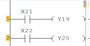
この内容に従い、以下のラダーをC言語のプログラムを
作成しました。
// 入力デバイスに関する設定部
#define X0021    (0x01 << 0)
#define X0022    (0x01 << 1)
#define X0034    (0x01 << 2)
#define X0035    (0x01 << 3)

#define   GET_X(DEVICE,NO)   (in_data & DEVICE)

byte in_no[] = { 21 , 22 , 34 , 35};
unsigned long in_data ;  // 入力Xの保持変数(32点数分)

// 出力デバイスに関する設定部
#define Y0018    (0x01 << 0)
#define Y0019    (0x01 << 1)
#define Y0025    (0x01 << 2)
#define Y0026    (0x01 << 3)

#define GET_Y(DEVICE,NO)   (out_data & DEVICE)
#define SET_Y_ON(DEVICE,NO)    out_data = out_data | DEVICE
#define SET_Y_OFF(DEVICE,NO)   out_data = out_data & ~DEVICE

byte out_no[] = { 18 , 19 , 25 , 26};
unsigned long out_data ;  // 出力Yの保持変数(32点数分)


// Arduino 起動時呼び出しプログラム
void setup(){
   for (byte i=0; i<sizeof(in_no); i++) {
     pinMode(in_no[i],INPUT);
   }
   for (byte i=0; i<sizeof(out_no); i++) {
     pinMode(out_no[i],OUTPUT);
   }
}

// Arduino 繰り返しプログラム
void loop(){
  output_update();
  input_update();

////////////////////////
// スキャンプログラム //
////////////////////////


  if (GET_X(X0021,21)){
    SET_Y_ON(Y0019,19);
  } else {
    SET_Y_OFF(Y0019,19);
  }

  if (GET_X(X0022,22)){
    SET_Y_ON(Y0025,25);
  } else {
    SET_Y_OFF(Y0025,25);
  }

////////////////////////

  output_update();
}

// standard function
// 入力情報の更新関数
void input_update() {
   in_data = 0;
   for (byte i=0; i<sizeof(in_no); i++) {
     if (digitalRead(in_no[i])==LOW) {
       in_data = in_data & ~(0x01 << i);
     } else {
       in_data = in_data | (0x01 << i);
     }
   }
}

// 出力情報の更新関数
void output_update() {
   for (byte i=0; i<sizeof( out_no ); i++) {
     if ( out_data & (0x01 << i) ) {
       digitalWrite( out_no[i], HIGH );
     } else {
       digitalWrite( out_no[i] , LOW );
     }
   }
}
こちらのプログラム長いですね。
入出力のプログラムはシステム部分です。
本来のラダー部は以下の部分です。
  if (GET_X(X0021,21)){
    SET_Y_ON(Y0019,19);
  } else {
    SET_Y_OFF(Y0019,19);
  }

  if (GET_X(X0022,22)){
    SET_Y_ON(Y0025,25);
  } else {
    SET_Y_OFF(Y0025,25);
  }